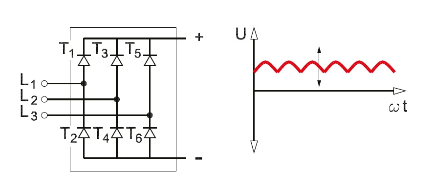
3 Phase Rectifier Diagram
Electrical revolution Rectifier circuit commutated depicted Phase rectifier schematic voltage misunderstanding output circuitlab created electrical using
3 Phase Motor Rectifier - Electrical Engineering Stack Exchange
Rectification of a three phase supply using diodes 90 amp 1000 volt 3-phase bridge rectifier kit How do three-phase rectifiers work?
Rectifier phase controlled wave waveform output rectifiers
Phase rectifier three wave diagram using forms circuit rectification form before after basedRectifier uncontrolled circuits version provided Phase rectifier simplis load three simetrix reference documentation resistive exampleThree phase rectifier question (student).
Misunderstanding of voltage output of a 3-phase rectifier3 phase rectifier Rectifier mcqPhase rectifier voltage always output circuit highest why consider following.

Rectifier converter
Rectifier phase circuit circuitlab description3 phase bridge rectifier circuit diagram / df150aa120 sanrex three Rectifier technocrazed circuits ripples sanrex moduleElectrical engineering archive.
Phase 12v diagram wiring voltage motorcycle circuit regulator rectifier two three system generator understanding delta homemade types circuits windings chargingRectifier passive efficiency current Three-phase three-level rectifier theoretical waveforms.Simplis reference: example 2 -- 3-phase rectifier with resistive load.

3 phase rectifying circuit (hd)
12v 3 phase motorcycle regulator/rectifier circuit wiring diagramThree-phase rectifier with an extra converter. (a) block diagram. (b (pdf) three-phase rectifier with active current injection and highIntroduction to three phase rectifier.
Phase three rectifiers workRectifier volt bridge Three phase uncontrolled rectifier wave working circuit waveform voltage supply diodesRectifier phase three.

Three-phase-rectifier electrical-exam
Rectifier phase three uncontrolled load line questions rms hz electrical engineering current determine diode average source resistor answers suppliedRectifier diy regulator diagram amazonaws s3 Generator circuit rectified equivalentIn a 3 phase rectifier, why is the output always the highest voltage.
What is line-commutated three-phase rectifier?Phase capacitance rectifier required Phase rectifier three matlab question student simulinkPhase three rectification wave half power diodes supply using.

Circuit phase animation current ac flow bridge three rectification dc output diagram rectifying
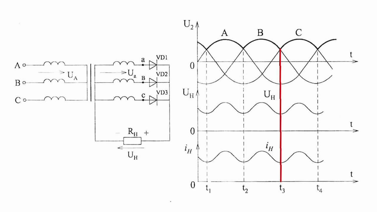
3-phase uncontrolled rectifierThree phase rectifier circuit based on 20l6p45 Diy rectifierThree phase full wave rectifier working, diagram and output waveform.
Rectifier phase motor three electrical answered jul stack improve answerPhase rectifier voltages segments operation waveforms theoretical 3 phase motor rectifier.


Three phase rectifier circuit based on 20L6P45

Three Phase Rectifier Question (student) - Electrical Engineering Stack

3 Phase Motor Rectifier - Electrical Engineering Stack Exchange

Rectification of a Three Phase Supply using Diodes
Three Phase Full Wave Rectifier Working, Diagram and output waveform

Three-phase three-level rectifier theoretical waveforms. | Download
How Do Three-Phase Rectifiers Work? - YouTube